The EC200U-CN is a compact and versatile module that combines LTE (Long-Term Evolution) and GPS (Global Positioning System) capabilities. Designed to provide robust wireless communication and precise location data, this module is ideal for a wide range of applications, including asset tracking, remote monitoring, and IoT devices.
Before we start working with the EC200U-CN module, we will need the following hardware and software:
Hardware and Software requirements
- Hardware:
- EC200U-CN LTE+GPS Module
- Arduino board (e.g., Arduino Uno, Arduino Mega)
- Appropriate power supply for the module
- Antennas for LTE and GPS
- Software:
- Arduino IDE (Integrated Development Environment)
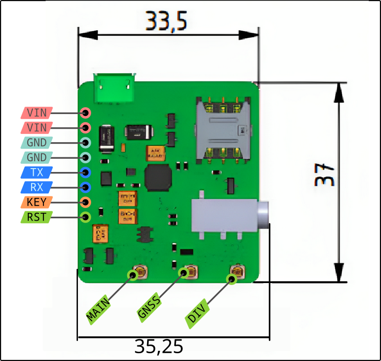
Pinout: 7Semi EC200U-CN Ultra-Compact Nano Module
 The EC200U-CN module features various pins that need to be properly connected. Below is a summary of the key pinout information for the EC200U-CN module:
VCC: Power source connection for the module.GND: Ground connection for the module.TX/RX (UART): Pins for serial communication between module and MircoControllers.RST: Use this pin to reset the module if necessary.MAIN: Connect the LTE antenna to this port for cellular communication.GNSS: Attach the GPS antenna to this port for accurate location data.
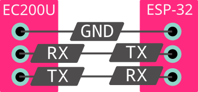
Connecting EC200U to ESP32 MircoController

Connections:
- EC200uCN GND to ESP32 GND.
- EC200uCN TX to ESP32 RX for data transmission. (Here, ESP32 pin 17)
- EC200uCN RX to ESP32 TX for data reception. (Here, ESP32 pin 16)
- 5V external power to EC200uCN’s Micor-USB port.
- ESP-32 Power:
- Powered via USB during code upload.
- Can also be powered by other sources based on requirements.
Code for EC200U and ESP32
#include <Arduino.h>
#include <HardwareSerial.h>

HardwareSerial ATSerial(1);

void setup() {
    Serial.begin(9600);
    ATSerial.begin(115200, SERIAL_8N1, 17, 16); // 17:RX, 16:TX
    Serial.setDebugOutput(true);
    Serial.setDebugOutput(true);
}


void loop() {
    while (ATSerial.available()) {
        Serial.write(ATSerial.read());
    }
    while (Serial.available()) {
        ATSerial.write(Serial.read());
    }
}
Quick code explanation:
Serial Communication Initialization:
The setup() function initializes two hardware serial ports. Serial.begin(9600) starts the serial communication at a baud rate of 9600 for the default Serial port. ATSerial.begin(115200, SERIAL_8N1, 17, 16) initializes the ATSerial port at a baud rate of 115200 with settings for 8 data bits, no parity, and 1 stop bit, using pins 17 (RX) and 16 (TX) on the Arduino.
Data Forwarding in Loop():
The loop() function contains two while loops that continuously check for available data on both serial ports and forwards the received data from one port to the other. When data is available on ATSerial, it is read and written to Serial using Serial.write(ATSerial.read()). Similarly, when data is available on Serial, it is read and written to ATSerial using ATSerial.write(Serial.read()).
Bidirectional Communication:
This code facilitates bidirectional communication between two hardware serial ports (Serial and ATSerial), allowing data to be sent and received between them.
Using the Serial connection with a PC to send a message to the ATSerial port:
- Connect Arduino to PC: Connect your Arduino board to your PC using a USB cable.
- Open Serial Monitor:
- Open the Arduino IDE.
- Go to Tools > Serial Monitor (or press Ctrl + Shift + M).
- Ensure the baud rate in the Serial Monitor matches the baud rate specified in the code (in this case, 9600).
- Ensure the option
Both NL & CRis selected.
- Open Serial Monitor:
- Send Messages:
- Type the message you want to send into the input field at the top of the Serial Monitor.
- Click “Send” or press Enter to transmit the message.
- The message will be sent via the Serial connection to the Arduino.
- Arduino Handling:
- The code in the loop() function reads data from the Serial port (Serial.available()) and writes it to the ATSerial port (ATSerial.write()).
- When a message is sent over Serail, it should automatically forward the message received from the Serial Monitor to the ATSerial port.
- When a message is sent from ATSerial, the loop reads the message and forward it to Serail Monitor.